What Is a Piston Compressor and How Does It Work?

A Piston Compressor is a mechanical device that raises gas pressure by moving a piston inside a cylinder. Its action resembles a carefully timed syringe. As the piston moves backward, the cylinder draws in air or another compatible gas. As it moves forward, the trapped gas is compressed and discharged through a valve. This simple cycle supports demanding work in workshops, manufacturing plants, refrigeration systems, and process equipment.

Understanding this machine requires more than memorizing its parts. The crankshaft, connecting rod, piston, cylinder, valves, seals, and lubrication system must work together precisely. A small valve problem can reduce output, increase heat, or create unusual noise. Maintenance records and operating measurements often reveal these issues before failure occurs. Pressure, temperature, vibration, and oil condition provide useful evidence for technicians and engineers.

Not every Piston Compressor behaves the same way. Single-stage models suit lighter pressure requirements, while multistage designs can reach higher pressures more efficiently. Reciprocating motion also creates pulsation, vibration, and wear, so installation quality matters. Pipe supports, cooling, alignment, and safety controls deserve close attention. The explanation may sound straightforward, but real equipment is less forgiving. Small assumptions can produce costly mistakes. This guide examines how a piston compressor works, why its components matter, and which practical factors influence performance, reliability, and service life. It also considers limitations that are sometimes overlooked, because efficient operation depends on both sound design and disciplined maintenance.
What Is a Piston Compressor and How Does It Work?

What Is a Piston Compressor?

A piston compressor is a positive-displacement machine that raises air or gas pressure inside a cylinder. It uses a piston, connecting rod, crankshaft, and inlet and outlet valves. The crankshaft turns, moving the piston back and forth. This motion changes the cylinder’s internal volume. Simple, but highly effective.

During the suction stroke

the piston moves away from the cylinder head. Lower pressure opens the inlet valve and draws gas inside. The piston then reverses direction. As the volume decreases, pressure and temperature rise. When the internal pressure exceeds the discharge-line pressure, the outlet valve opens. Compressed gas leaves through the discharge port. A seal around the piston limits leakage, although no seal remains perfect forever.

Piston compressors may use one cylinder or several stages.

Multistage designs compress gas gradually, often with cooling between stages. Lubricated models reduce friction, while oil-free models keep oil away from the compression chamber. In practical inspections, unusual knocking, hot discharge air, or frequent cycling deserves attention. These signs can point to worn valves, poor lubrication, restricted airflow, or incorrect operating pressure. Noise alone does not prove failure. That assumption can mislead maintenance decisions. Engineers should check pressure readings, temperature, vibration, and service records together. The design is dependable, yet it needs careful adjustment and regular inspection.
What Are the Main Parts of a Piston Compressor?

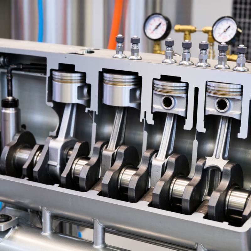
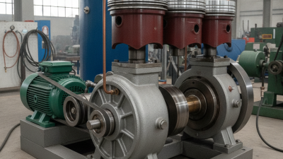
A piston compressor uses a reciprocating piston to compress air or gas inside a cylinder. Its main parts work as one mechanical system. The cylinder provides the compression chamber, while the piston moves back and forth inside it. Piston rings help seal the gap and reduce leakage. A connecting rod links the piston to the crankshaft. When the motor turns the crankshaft, it changes rotary motion into piston movement.

The inlet and discharge valves control gas flow. During the intake stroke, the inlet valve opens and draws air into the cylinder. The valve then closes as the piston moves upward. Pressure rises, and the discharge valve opens when compressed air leaves the chamber. The crankcase supports the crankshaft and often stores lubricating oil. Bearings reduce friction, while a flywheel helps maintain steady movement. Some systems also use cooling fins, an air receiver, and pressure controls. The design looks simple. It is not always forgiving.

Tips: Check oil levels, valve condition, and ring wear during routine maintenance. Listen for knocking, unusual vibration, or frequent pressure loss. These signs can point to loose parts or damaged seals. Keep the intake filter clean, because restricted airflow increases operating strain. Drain moisture from the receiver regularly. In workshop inspections, technicians sometimes focus on the motor and overlook the valves. That mistake can waste energy and reduce output. Always follow the equipment manual and isolate power before opening the compressor.

What Is a Piston Compressor and How Does It Work?

A piston compressor uses a reciprocating piston inside a cylinder to reduce gas volume and increase its pressure. The crankshaft converts rotary motion into piston motion, while the suction and discharge valves control gas flow.

Main Parts of a Piston Compressor

  • Cylinder: Provides the chamber in which the gas is compressed.
  • Piston: Moves back and forth to draw in and compress the gas.
  • Suction Valve: Opens during the intake stroke to let low-pressure gas enter.
  • Discharge Valve: Opens when cylinder pressure exceeds discharge-line pressure.
  • Connecting Rod: Transfers motion between the piston and crankshaft.
  • Crankshaft: Converts rotary motor power into reciprocating piston motion.
  • Clearance Volume: Small space remaining at the end of the compression stroke, which affects volumetric efficiency.

The chart shows representative absolute pressures for a single-stage reciprocating compressor operating between approximately 1 bar suction pressure and 8 bar discharge pressure. Actual values vary with compressor design, operating speed, valve timing, temperature, and clearance volume.

How Does a Piston Compressor Work Step by Step?

A piston compressor uses a reciprocating piston to compress gas inside a cylinder. Its working cycle resembles a syringe, but the pressure and heat are far higher. The U.S. Department of Energy reports that compressed air can represent about 10% of industrial electricity use. Small operating mistakes therefore deserve attention.

The process starts when the crankshaft turns and pulls the piston downward. The inlet valve opens, allowing atmospheric air into the cylinder. The piston then reverses direction. Both valves close, trapping the air. As the piston rises, the cylinder volume decreases and air pressure increases. When cylinder pressure exceeds discharge-line pressure, the outlet valve opens. Compressed air leaves the cylinder and enters a receiver or pipeline. The piston moves down again, and the cycle repeats.

One cycle at a time.

During compression, air temperature rises sharply. Cooling fins, intercoolers, and lubricating oil help control that heat. The U.S. Department of Energy’s Improving Compressed Air System Performance guide notes that leaks may waste 20–30% of compressor output. A technician may hear a faint hiss near a fitting, yet that small sound can run continuously. Pressure switches, filters, and check valves also influence performance. The sequence looks clean on paper, but valve wear and poor drainage complicate real operation. ISO 1217 testing methods measure compressor performance under defined conditions, although field results can differ. That difference deserves honest attention.

What Is a Piston Compressor and How Does It Work? - How Does a Piston Compressor Work Step by Step?

Step Component or Concept Operating Stage How It Works
1 Piston Compressor Basic Definition A piston compressor, also called a reciprocating compressor, uses one or more pistons moving inside cylinders to reduce the volume of gas and increase its pressure.
2 Prime Mover Power Input An electric motor or another mechanical power source rotates the crankshaft. The crankshaft converts rotary motion into the reciprocating motion required by the pistons.
3 Crankshaft and Connecting Rod Motion Transfer The connecting rod links the crankshaft to the piston. As the crankshaft turns, the rod drives the piston back and forth within the cylinder.
4 Cylinder Compression Chamber The cylinder provides a controlled chamber in which the piston changes the gas volume. The cylinder head normally contains the inlet and discharge valve assemblies.
5 Inlet Valve Gas Admission When cylinder pressure falls below inlet pressure, the inlet valve opens and gas flows into the cylinder. The valve closes when the piston begins the compression stroke.
6 Suction Stroke Piston Moving Outward The piston moves away from the cylinder head, increasing the cylinder volume and reducing its pressure. This pressure difference draws gas through the inlet valve.
7 Compression Stroke Piston Moving Inward The piston reverses direction and moves toward the cylinder head. Both valves remain closed initially, so the trapped gas is compressed into a smaller volume and its pressure and temperature rise.
8 Discharge Valve Gas Delivery When cylinder pressure becomes higher than the discharge-line pressure, the discharge valve opens. The compressed gas flows into the receiver, pipeline, or downstream process equipment.
9 Clearance Volume End of Compression A small amount of gas remains in the cylinder when the piston reaches the end of its stroke. This clearance prevents mechanical contact between the piston and cylinder head but slightly reduces volumetric efficiency.
10 Pressure Pulsation Flow Characteristic Because gas is delivered in individual piston cycles rather than as a perfectly continuous stream, reciprocating compressors can produce pressure pulsations. Pulsation dampeners may be used to smooth the flow.
11 Single-Stage Design Compression Arrangement In a single-stage compressor, the gas is compressed from inlet pressure to discharge pressure in one cylinder stage. This arrangement is generally suited to relatively moderate pressure ratios.
12 Multi-Stage Design Higher Pressure Service In a multi-stage compressor, gas is compressed in successive cylinders. Intercooling between stages can reduce gas temperature, lower compression work, and improve operating efficiency.
13 Lubrication System Friction and Wear Control Oil-lubricated designs use oil to reduce friction and wear at moving parts. Oil-free designs use specialized materials, coatings, or sealing arrangements where the compressed gas must remain free from oil contamination.
14 Cooling System Temperature Management Compression generates heat. Air-cooled fins or water-cooled jackets and intercoolers help control cylinder, valve, and discharge-gas temperatures.
15 Receiver and Controls System Regulation A receiver stores compressed gas and helps reduce pressure fluctuations. Controls may start or stop the compressor, unload the cylinders, or regulate output according to demand.
16 Complete Cycle Repeatable Operation The operating cycle repeats as suction, compression, and discharge events occur on each piston stroke. Capacity depends on displacement, operating speed, cylinder arrangement, pressure conditions, and volumetric efficiency.

What Types of Piston Compressors Are Available?

A piston compressor uses a reciprocating piston to compress gas inside a cylinder. The piston moves downward to draw gas through an inlet valve. It then moves upward and forces compressed gas through an outlet valve. This simple cycle remains dependable in workshops, laboratories, and industrial systems.

What types of piston compressors are available?

Single-stage models compress air once and suit light tools, inflation, and moderate pressure tasks.

Two-stage models compress air in separate steps, producing higher pressure with improved temperature control.

Single-acting compressors compress gas on one piston side, while double-acting designs use both sides for greater output.

Lubricated models use oil to reduce friction and wear. Oil-free models avoid oil contact, which helps protect sensitive air applications.

Diaphragm compressors use a flexible membrane instead of direct piston contact. They are useful when gas purity matters.

Tips: Match the compressor type to pressure, airflow, duty cycle, and air cleanliness requirements. Check the receiver size, noise level, maintenance access, and operating temperature. A larger unit is not always better.

In my experience, undersized compressors run continuously and wear faster. However, choosing the most powerful model can waste energy. Actual demand may be lower than expected, so measure usage before purchasing.

Regularly inspect valves, seals, filters, and safety controls. Small faults become expensive problems.

Where Are Piston Compressors Used?

Piston compressors are used wherever compressed air or gas must be delivered at a controlled pressure. Their reciprocating pistons suit workshops, factories, laboratories, and service vehicles. A piston moves inside a cylinder, reducing the space available for gas. Pressure rises, and a valve directs the compressed gas into a receiver or process line.

In workshops, these compressors power impact wrenches, spray equipment, nailers, and air brakes. Small units often sit beneath a workbench, while larger machines support production lines. They are useful when demand changes during the day. The receiver stores air between operating cycles. This reduces constant motor operation.

Piston compressors also serve refrigeration systems, natural gas processing, medical air systems, and chemical plants. In refrigeration equipment, the compressor moves refrigerant between low and high-pressure sides. Medical installations require clean, dry air and careful monitoring. That detail is easy to underestimate. Moisture, oil carryover, and worn valves can affect equipment performance.

From practical maintenance work, I have seen heat and vibration reveal problems early. Unusual knocking may indicate worn bearings, loose components, or poor lubrication. Operators should check filters, drain condensate, and follow pressure limits. Piston compressors can be noisy and produce pulsating flow, especially at high output. For some applications, that behavior is inconvenient. Engineers may add mufflers, vibration mounts, or pulsation dampers, although these solutions increase system complexity.